![]()
![]()
![]()
![]()

![]()
![]()
![]()
|
|
|
|
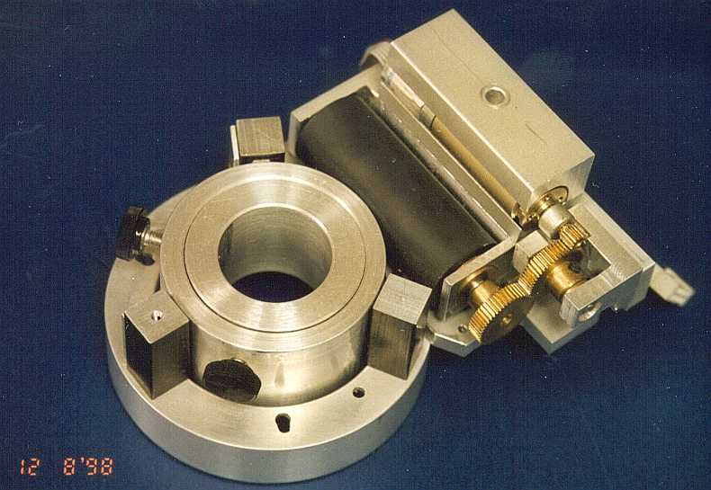
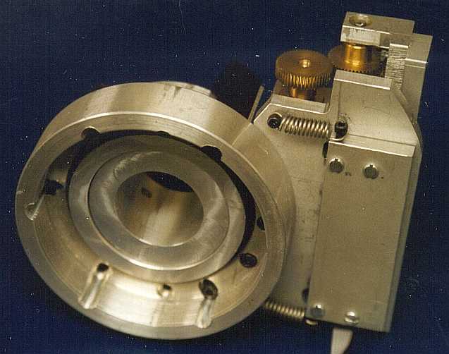
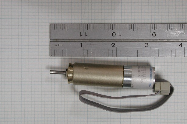
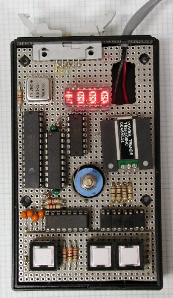
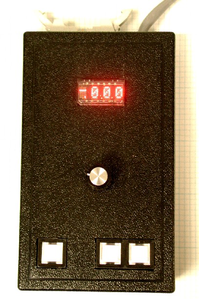
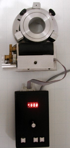
– with Manual & RS-232 Control and Digital DisplayOne of the major complaints most people have about Meade SCT's, is mirror shift when focusing. Generally speaking, when using a camera or visually with an eyepiece, the shift of the image is not as much a problem as an annoyance. However, due to the small field of view of a CCD camera, image shift is likely to cause the object of interest to leave the CCD detection area. Image shift on the SCT is due to the way focusing is done. In a conventional telescope focusing is accomplished by moving the eyepiece so the focal point of the eyepiece and the focal point of the telescope objective are at the same place. In an SCT, the focus knob moves the primary mirror along the baffle tube – thus moving the focal point of the telescope to meet the focal point of the eyepiece. Since the focus mechanism only comes in contact with one side of the mirror, the mirror tends to "rock" as you change focus directions – thus causing the image shift. To overcome this problem, users have turned to a "zero shift focuser". This is a unit that attaches to the back of a SCT, and has a draw tube that moves in and out to achieve fine focus. Rough focus is still done by the focus knob on the SCT – although some users will insert the "lock down bolt" to keep the primary mirror from moving at all. My complaint with zero shift focusers currently available, is they are designed for use with a person at the telescope. My long term goal is to operate the telescope and peripherals from inside my house via a computer link. To that end I have built a zero shift focuser that is controlled by an MicroChip 16F873 micro-controller. The 16F873 will allow for remote control via RS-232 of all functions (set 0, move + x thousandths, move – x thousandths, show position). While using the zero shift focuser at the telescope, the observer will be able to use many of the same functions, with position being shown by an LED display. Actual movement is provided by a small dc motor with internal (19,813:1) and external gear (4:1) reduction. The motor also has an optical encoder integrated into it that is used for position detection. The control unit has 3 buttons that control operation as follows:
RS-232 operation is as follows:
The software was written in standard MicroChip assembler, but was compiled using TechTools, Inc CVASM. The software can be downloaded here. This project was originally started in 1992. The ZSF pictured in the first 2 pictures was built at that time. I do not have any of the construction drawings available at this time, but hope to be able to provide them in the future. The schematic is available here.
|
|
Please address general comments to web@dv-fansler.com This page was last modified:
01/22/14 |