![]()
![]()
![]()
![]()

![]()
![]()
![]()
![]()
![]()
|
|
|
|
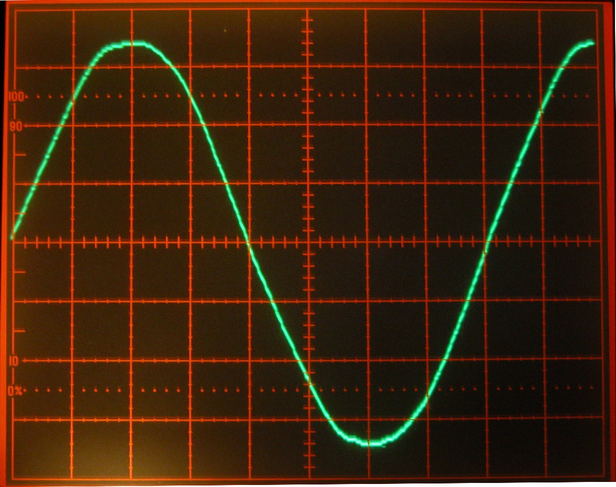
To understand how you dim a 110VAC light, we need to take a look at a 110VAC 60Hz wave as seen from a typical US wall socket.
The first dimmers were mechanical in that they simply changed the height of the wave, thus the RMS - a Veriac® was such a device (sort of a big rheostat). Later motors were added, which was nice, but they were still very expensive and mechanically limited as to how fast they could fade.
Today dimming is typically done using phase control via a pair of SCRs (silicon controlled rectifier) or a Triac. A more detailed description is below, but for now think of them as being high speed electronic switches. A full cycle of 60Hz is shown here. This is divided up into 256 steps per half cycle on the x-axis. While the formula does not show up well, to determine height of a sine wave, use f(y) = Asin(ωtt). ω is the angular frequency in radians/second (2π for 1 cycle), t is time, and A is the maximum amplitude of the wave
If you only wanted 1/2 full intensity from a light, then you would only need 1/2 of each half cycle of an AC wave. As is shown in the graph to the left, voltage remains at 0 until a half cycle reaches the mid-point. At this time, the triac is turned on and voltage flows through the light. As the wave reaches 0V, the triac turns off and stays off until the mid-point of the negative half cycle. Again the triac is turned on and voltage is passed through the light. By controlling when in a phase the triac is turned on, the amount of voltage through a light is determined and thus its brightness.
If you only wanted 1/4full intensity from a light, then you would only need 1/4 of each half cycle of an AC wave. As is shown in the graph to the left, voltage remains at 0 until a half cycle reaches the 3/4 mark. At this time, the triac is turned on and voltage flows through the light. As the wave reaches 0V, the triac turns off and stays off until the 3/4-point of the negative half cycle. Again the triac is turned on and voltage is passed through the light.
If you want 3/4 full intensity from a light, then you would only need 3/4 of each half cycle of an AC wave. As is shown in the graph to the left, voltage remains at 0 until a half cycle reaches the 1/4-point. At this time, the triac is turned on and voltage flows through the light. As the wave reaches 0V, the triac turns off and stays off until the 1/4-point of the negative half cycle. Again the triac is turned on and voltage is passed through the light. So the light would receive 3/4 of each half cycle.
By controlling when (in a half cycle) the triac is turned on, the average power through a light is controlled - and thus its brightness.
SCR and Triacs A SCR (silicon controlled rectifier) allows control of AC waves.
The symbol for an SCR looks like a diode with an extra connection.
SCR's act like a
In order to control the positive half and the negative half of an AC wave, two SCRs must be used, in parallel and with the Anode of one connected to the Cathode of the other.
A Triac is basically two SCRs in one package. Since current can flow in either direction, the terms anode and cathode are replaced with Main Terminal 1 and Main Terminal 2. Gate remains the same. Like SCRs, triacs will quit conducting when the voltage reaches 0. For this reason, SCRs and Triacs are only good for AC voltage. If used with DC voltage, they will turn on, but never turn off until the supply voltage is removed.
|
|
Please address general comments to web@dv-fansler.com This page was last modified:
01/22/14 |
 This
image was taken from a Tektronix 468 Digital Storage Oscilloscope. Each
vertical line represents 50V and each horizontal line represents 2 milliseconds.
From where the wave starts (rising from the center line) to where it again is
rising across the center line is just over 8 horizontal divisions, or 16,67ms.
This is one complete cycle and occurs 60 times every second on the US power
grid. In dimming we are concerned with what happens every half cycle, or
every 8.33ms. Notice that the wave is about 7 vertical divisions tall.
At 50V/division, that gives this wave 350V peak to peak voltage. Since AC
waves are not constant like DC, AC waves are typically measured by an average of
the time they are above (or below) 0V. Root mean square or RMS is the
average used, so this wave would be ~115VAC RMS.
This
image was taken from a Tektronix 468 Digital Storage Oscilloscope. Each
vertical line represents 50V and each horizontal line represents 2 milliseconds.
From where the wave starts (rising from the center line) to where it again is
rising across the center line is just over 8 horizontal divisions, or 16,67ms.
This is one complete cycle and occurs 60 times every second on the US power
grid. In dimming we are concerned with what happens every half cycle, or
every 8.33ms. Notice that the wave is about 7 vertical divisions tall.
At 50V/division, that gives this wave 350V peak to peak voltage. Since AC
waves are not constant like DC, AC waves are typically measured by an average of
the time they are above (or below) 0V. Root mean square or RMS is the
average used, so this wave would be ~115VAC RMS.
 diode with an ON switch. That is they will only allow the
flow of electrons in one direction thru the device. The Gate is an on
switch, that determines when in an AC wave the SCR will start conducting.
All that is needed is an ON pulse. A SCR will stop conducting when the AC
voltage reaches 0 V.
diode with an ON switch. That is they will only allow the
flow of electrons in one direction thru the device. The Gate is an on
switch, that determines when in an AC wave the SCR will start conducting.
All that is needed is an ON pulse. A SCR will stop conducting when the AC
voltage reaches 0 V.