![]()
![]()
![]()
![]()

![]()
![]()
![]()
![]()
|
|
|
|
Please note that these circuits contain lethal voltages. If you have any questions about what you are doing, ask someone who knows! I can not assume any responsibility for harm that may come to anyone working with these or similar circuits! Control Circuits
Here is a rather unique circuit that uses only one SCR to control both the positive and negative cycles of an AC wave. By changing the value of R (via a potentiometer), the charging time of capacitor C is either increased or decreased. When the trigger voltage for the SCR is reached at the junction of R & C, the SCR is turned on.
This is another simple circuit, this time for a Triac. Due to the bi-directional nature of a triac nothing special has to be done to control both halves of an AC wave. Again, a variable resistor, R1, determines how fast the charge on capacitor C1 occurs. When the voltage at the junction of R1 and C1 reaches the trigger voltage for the triac, the triac conducts providing power to the load. This is the basic circuit for the light dimmers you buy at a home improvement store for use in your house.
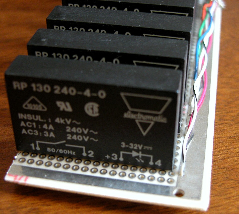
Controlling 110VAC with 5VDCUsing a microprocessor to control an AC load is done everyday in our modern lives. Your microwave is one such example that comes to mind. The problem in controlling and AC load with a microprocessor is a microprocessor operates typically from 5vdc which does not play well with 110vac! The simplest means is to use a solid state relay (SSR). These are encapsulated devices which contain a triac and an opto-isolator which reduces the chances of 110vac getting back into our microprocessor. Most of these devices are termed "zero crossing". meaning they will only turn on right after a new half cycle starts. Zero crossing SSRs are useless if you intend to do any dimming. For dimming you need "random" SSRs. Here is an schematic of a low temperature controller using an SSR. Below is an example of connecting a triac to a microprocessor. It should be noted that the microprocessor could be replaced with any 5vdc logic device (such as the 74HC595 often used in computer Christmas light shows). Looking at the circuit, the I/O pin of the microprocessor provides a 0v or a 5vdc signal. This signal will turn on the LED inside the MC3010 opto-isolator. The 680Ω resistor limits the current that can be drawn from the I/O pin - if you draw too much current you will damage the microprocessor (or any other logic chip) as well as burning out the LED. Also inside the MC3010 is a photo sensitive device (diode, transistor, etc.) that turns on when the LED is on. This allows voltage from the 110VAC hot leg to flow to the gate on the triac, thus turning the triac on. The 150Ω resistor again limits current flow through the MC3010 and the gate of the triac. The circuit breaker is to limit current through the AC circuit. The inductor slows the rise time of the AC wave when it turns on. In turn this provides two functions: 1) it reduces EMI (electromagnetic interference) created by the sudden rise in voltage in the wires, and 2) stops light bulb filaments from rattling. When you turn the typical home dimmer down low, you can hear a buzz in the light fixture - that is the filaments rattling as the voltage is suddenly applied to the bulb.
Dimming with a microprocessorInstead of providing a circuit in the page, here is a link to a circuit in PDF format. This opens in a separate window making it easy to follow along. Looking at the bottom of the circuit is a center tapped transformer - this provides rectified AC to DC which is regulated by U3, a voltage regulator. The transformer also has a pair of 1N4001 diodes providing a rectified AC wave (the negative half of the wave is inverted so that both half cycles are positive). The combined output of the two diodes is connected to an op amp (U3A) which is setup to give a small pulse every time the rectified wave gets close to 0v. This pulse is then cleaned up by a pair of Schmitt triggers (U4A, U4B). The output of this circuit provides a pulse for every zero crossing of the AC wave (120 times/second) - something we have to know for dimming! The zero crossing signal is feed to an interrupt on the PIC processor to provide a time base reference. Six analog inputs (0-5vdc) provide information on how bright (or what percentage power) is desired from the associated triac. 0v would mean off, where as 5vdc is fully on. The input voltages are converted to an 8 bit digital signal within the PIC processor. An internal timer (TMR0) provides an interrupt every 32.5us. This causes an 8 bit counter to be incremented. The 8 bit value of the analog inputs are compared to the 8 bit counter - if any 8 bit value is less than the 8 bit counter then the corresponding output is turned on. This process continues for8.33ms - one half an 60Hz wave. Just before the end of the 8.33ms time, the 8 bit counter will have reached full count (255) and will stay there until a zero crossing is detected. When a zero crossing is detected, the 8 bit counter is reset to 0 and the process of incrementing the counter every 32.5us starts over. Each output on J2 would go to a MC3010 opto-isolator which would drive a triac and its load, as shown in the circuit above. While this is a perfectly good circuit, I have not written the software - this will be done in the near future. |
|
Please address general comments to web@dv-fansler.com This page was last modified:
01/22/14 |